如何基于blockMesh生成的圆柱网格添加边界层
-
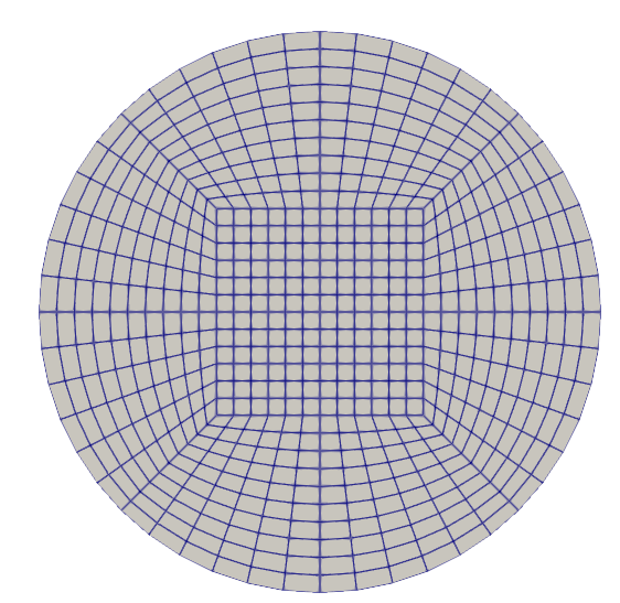
各位大佬好,我通过如下的blockMesh生成了一个圆柱型网格(O型切分),但想针对壁面wallPipe添加5层边界层进行湍流模拟,我使用的blockMeshDict和snappyHexMeshDict文件如下,blockMesh可以生成较好的网格,但是使用snappyHexMesh -overwrite命令后,网格没有任何变化,想请教各位,OpenFOAM有没有其他添加边界层的方法呢?或者我目前的方法有什么问题?
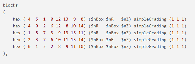
/*--------------------------------*- C++ -*----------------------------------*\
| =========                 |                                                 |
| \\      /  F ield         | OpenFOAM: The Open Source CFD Toolbox           |
|  \\    /   O peration     | Version:  5                                     |
|   \\  /    A nd           | Web:      www.OpenFOAM.org                      |
|    \\/     M anipulation  |                                                 |
\*---------------------------------------------------------------------------*/
FoamFile
{
    version     2.0;
    format      ascii;
    class       dictionary;
    object      blockMeshDict;
}
// * * * * * * * * * * * * * * * * * * * * * * * * * * * * * * * * * * * * * //

convertToMeters 1;

trueradius 0.025;

radius      #calc "sqrt(2.0)*0.5*$trueradius";//圆柱半径
radiusNeg   #calc "-sqrt(2.0)*0.5*$trueradius";
box         0.0092; // boxNeg定义中间长方体block的范围    0.12
boxNeg     -0.0092;
zMax        0.5;//100;//zMax和zMin定义圆柱体的长度
zMin        0.0;

nR          10;//扇形block半径上的节点数          6
nBox        12;//矩形block正方形边上的节点数     8
nZ          180;//5000;//轴向方向上的节点数


verbose no;

geometry
{
    cylinder
    {
        type      searchableCylinder;
        point1    (0 0 -0.1);//由point1和point2构成的区域要大于zMax和zMin构成的区域
        point2    (0 0  1000.1);//100.1);
        radius    $trueradius;
    }
}

scale 1;


vertices
(
    // Inner
    ($boxNeg $boxNeg $zMin)//0
    ($box    $boxNeg $zMin)//1
    ($boxNeg $box    $zMin)//2
    ($box    $box    $zMin)//3

    // Outer block points
    project ($radiusNeg $radiusNeg $zMin) (cylinder)//4
    project ($radius    $radiusNeg $zMin) (cylinder)//5
    project ($radiusNeg $radius    $zMin) (cylinder)//6
    project ($radius    $radius    $zMin) (cylinder)//7

    // Inner
    ($boxNeg $boxNeg $zMax)//8
    ($box    $boxNeg $zMax)//9
    ($boxNeg $box    $zMax)//10
    ($box    $box    $zMax)//11

    // Outer block points
    project ($radiusNeg $radiusNeg $zMax) (cylinder)//12
    project ($radius    $radiusNeg $zMax) (cylinder)//13
    project ($radiusNeg $radius    $zMax) (cylinder)//14
    project ($radius    $radius    $zMax) (cylinder)//15
);

blocks
(
    hex ( 4  5  1  0 12 13  9  8) ($nBox $nR   $nZ) simpleGrading (1 1 1)
    hex ( 4  0  2  6 12  8 10 14) ($nR   $nBox $nZ) simpleGrading (1 1 1)
    hex ( 1  5  7  3  9 13 15 11) ($nR   $nBox $nZ) simpleGrading (1 1 1)
    hex ( 2  3  7  6 10 11 15 14) ($nBox $nR   $nZ) simpleGrading (1 1 1)
    hex ( 0  1  3  2  8  9 11 10) ($nBox $nBox $nZ) simpleGrading (1 1 1)
);

edges
(
    project  4  5 (cylinder)
    project  7  5 (cylinder)
    project  6  7 (cylinder)
    project  4  6 (cylinder)
    project 12 13 (cylinder)
    project 13 15 (cylinder)
    project 12 14 (cylinder)
    project 14 15 (cylinder)
);

boundary
(
    bottom
    {
    	type patch;  // patch
    	faces
    	(
	     (0 1 3 2)
	     (0 2 6 4)
	     (0 1 5 4)
	     (1 5 7 3)
	     (2 3 7 6)
	);
    }

    outlet
    {
    	type patch;  // patch
    	faces
    	(
	     (8   9  11  10)
	     (8  10  14  12)
	     (8   9  13  12)
	     (9  13  15  11)
	     (10 11  15  14)
	);
    }

    wallPipe
    {
    	type wall;
    	faces
    	(
	     (4  12  14  6)
	     (4   5  13 12)
	     (5  13  15  7)
	     (6   7  15 14)
	);
    }
);

mergePatchPairs
(
);


// ************************************************************************* //
snappyHexMeshDict文件
/*--------------------------------*- C++ -*----------------------------------*\
| =========                 |                                                 |
| \\      /  F ield         | OpenFOAM: The Open Source CFD Toolbox           |
|  \\    /   O peration     | Version:  v2206                                 |
|   \\  /    A nd           | Website:  www.openfoam.com                      |
|    \\/     M anipulation  |                                                 |
\*---------------------------------------------------------------------------*/
FoamFile
{
    version     2.0;
    format      ascii;
    class       dictionary;
    object      snappyHexMeshDict;
}
// * * * * * * * * * * * * * * * * * * * * * * * * * * * * * * * * * * * * * //

// Which of the steps to run
castellatedMesh false;
snap            false;
addLayers       true;


// Geometry. Definition of all surfaces. All surfaces are of class
// searchableSurface.
geometry
{}


// Settings for the castellatedMesh generation.
castellatedMeshControls
{

    // Refinement parameters
    // ~~~~~~~~~~~~~~~~~~~~~

    // If local number of cells is >= maxLocalCells on any processor
    // switches from from refinement followed by balancing
    // (current method) to (weighted) balancing before refinement.
    maxLocalCells 100000;

    // Overall cell limit (approximately). Refinement will stop immediately
    // upon reaching this number so a refinement level might not complete.
    // Note that this is the number of cells before removing the part which
    // is not 'visible' from the keepPoint. The final number of cells might
    // actually be a lot less.
    maxGlobalCells 2000000;

    // The surface refinement loop might spend lots of iterations refining just a
    // few cells. This setting will cause refinement to stop if <= minimumRefine
    // are selected for refinement. Note: it will at least do one iteration
    // (unless the number of cells to refine is 0)
    minRefinementCells 0;

    // Allow a certain level of imbalance during refining
    // (since balancing is quite expensive)
    // Expressed as fraction of perfect balance (= overall number of cells /
    // nProcs). 0=balance always.
    maxLoadUnbalance 0.10;

    // Number of buffer layers between different levels.
    // 1 means normal 2:1 refinement restriction, larger means slower
    // refinement.
    nCellsBetweenLevels 1;


    // Explicit feature edge refinement
    // ~~~~~~~~~~~~~~~~~~~~~~~~~~~~~~~~

    // Specifies a level for any cell intersected by explicitly provided
    // edges.
    // This is a featureEdgeMesh, read from constant/triSurface for now.
    // Specify 'levels' in the same way as the 'distance' mode in the
    // refinementRegions (see below). The old specification
    //      level   2;
    // is equivalent to
    //      levels  ((0 2));

    features
    ();


    // Surface based refinement
    // ~~~~~~~~~~~~~~~~~~~~~~~~

    // Specifies two levels for every surface. The first is the minimum level,
    // every cell intersecting a surface gets refined up to the minimum level.
    // The second level is the maximum level. Cells that 'see' multiple
    // intersections where the intersections make an
    // angle > resolveFeatureAngle get refined up to the maximum level.

    refinementSurfaces
    {}

    // Feature angle:
    // - used if min and max refinement level of a surface differ
    // - used if feature snapping (see snapControls below) is used
    resolveFeatureAngle 30;


    // Region-wise refinement
    // ~~~~~~~~~~~~~~~~~~~~~~

    // Specifies refinement level for cells in relation to a surface. One of
    // three modes
    // - distance. 'levels' specifies per distance to the surface the
    //   wanted refinement level. The distances need to be specified in
    //   increasing order.
    // - inside. 'levels' is only one entry and only the level is used. All
    //   cells inside the surface get refined up to the level. The surface
    //   needs to be closed for this to be possible.
    // - outside. Same but cells outside.

    refinementRegions
    {}

    // Mesh selection
    // ~~~~~~~~~~~~~~

    // After refinement patches get added for all refinementSurfaces and
    // all cells intersecting the surfaces get put into these patches. The
    // section reachable from the location(s)InMesh is kept.
    // NOTE: This point should never be on a face, always inside a cell, even
    // after refinement.
    //
    // There are two different ways of specifying the regions to keep:
    // 1. a single locationInMesh. All the 'zoned' surfaces are marked as such
    //    in the refinementSurfaces with the faceZone and cellZone keywords.
    //
    // or
    //
    // 2. multiple locationsInMesh, with per location the name of the cellZone.
    //    This uses walking to determine zones and automatically creates
    //    faceZones on the outside of cellZones.


    // Ad 1. Specify a single location and how to treat faces inbetween
    //       cellZones
    locationInMesh (5 0.28 0.43);

    // Whether any faceZones (as specified in the refinementSurfaces)
    // are only on the boundary of corresponding cellZones or also allow
    // free-standing zone faces. Not used if there are no faceZones.
    allowFreeStandingZoneFaces true;
}


// Settings for the snapping.
snapControls
{
    // Number of patch smoothing iterations before finding correspondence
    // to surface
    nSmoothPatch 3;

    // Maximum relative distance for points to be attracted by surface.
    // True distance is this factor times local maximum edge length.
    // Note: changed(corrected) w.r.t 1.7.x! (1.7.x used 2* tolerance)
    tolerance 2.0;

    // Number of mesh displacement relaxation iterations.
    nSolveIter 30;

    // Maximum number of snapping relaxation iterations. Should stop
    // before upon reaching a correct mesh.
    nRelaxIter 5;

}


// Settings for the layer addition.
addLayersControls
{
    // Are the thickness parameters below relative to the undistorted
    // size of the refined cell outside layer (true) or absolute sizes (false).
    relativeSizes false;

    // Layers defined by overall thickness and expansion ratio
//    thickness           0.7e-3;
    firstLayerThickness 2e-3;
	expansionRatio 1.2;

    // Minimum overall thickness of total layers. If for any reason layer
    // cannot be above minThickness do not add layer.
    // If relativeSizes this is relative to undistorted size of cell
    // outside layer..
    minThickness 0.0001e-3;


    // Per final patch (so not geometry!) the layer information
    layers
    {
        sidewalls
        {
            nSurfaceLayers 3;
        }

    }

    // If points get not extruded do nGrow layers of connected faces that are
    // also not grown. This helps convergence of the layer addition process
    // close to features.
    // Note: changed(corrected) w.r.t 1.7.x! (didn't do anything in 1.7.x)
    nGrow 0;

    // Advanced settings


    // Static analysis of starting mesh

        // When not to extrude surface. 0 is flat surface, 90 is when two faces
        // are perpendicular
        featureAngle 130;

        // When to merge patch faces. Default is featureAngle
        //mergePatchFacesAngle 45;

        // Do not extrude around sharp edge if not both faces are extruded.
        // Default is 0.5*featureAngle. Set to -180 always attempt extrusion
        layerTerminationAngle -180;

        // Stop layer growth on highly warped cells
        maxFaceThicknessRatio 0.5;


    // Patch displacement

        // Number of smoothing iterations of surface normals
        nSmoothSurfaceNormals 1;

        // Smooth layer thickness over surface patches
        nSmoothThickness 10;


    // Medial axis analysis

        // Angle used to pick up medial axis points
        // Note: changed(corrected) w.r.t 1.7.x! 90 degrees corresponds to 130
        // in 1.7.x.
        minMedialAxisAngle 90;

        // Reduce layer growth where ratio thickness to medial
        // distance is large
        maxThicknessToMedialRatio 0.3;

        // Number of smoothing iterations of interior mesh movement direction
        nSmoothNormals 3;

        // Optional: at non-patched sides allow mesh to slip if extrusion
        // direction makes angle larger than slipFeatureAngle. Default is
        // 0.5*featureAngle.
        slipFeatureAngle 30;


    //// Motion solver instead of default medial axis
    //
    //    //- Use displacementMotionSolver to shrink mesh
    //    meshShrinker displacementMotionSolver;
    //
    //    //- Use laplacian for shrinking
    //    solver displacementLaplacian;
    //
    //    displacementLaplacianCoeffs
    //    {
    //        diffusivity quadratic inverseDistance ("m.*");
    //    }


    // Mesh shrinking

        // Maximum number of snapping relaxation iterations. Should stop
        // before upon reaching a correct mesh.
        nRelaxIter 5;

        // Create buffer region for new layer terminations
        nBufferCellsNoExtrude 0;

        // Overall max number of layer addition iterations. The mesher will
        // exit if it reaches this number of iterations; possibly with an
        // illegal mesh.
        nLayerIter 50;

        // Overall number of outer layer of iterations. Default is 1 -> all
        // layers are added in one pass.
        nOuterIter 3;
}

// Generic mesh quality settings. At any undoable phase these determine
// where to undo.
meshQualityControls
{
    // Specify mesh quality constraints in separate dictionary so can
    // be reused (e.g. checkMesh -meshQuality)
    #include "meshQualityDict"

    // Advanced

        // Number of error distribution iterations
        nSmoothScale 4;
        // amount to scale back displacement at error points
        errorReduction 0.75;
}


// Advanced

// Merge tolerance. Is fraction of overall bounding box of initial mesh.
// Note: the write tolerance needs to be higher than this.
mergeTolerance 1e-6;

debugFlags
(
    //mesh
);

// Write flags
writeFlags
(
    //layerFields     // write volScalarField for layer coverage
);

// ************************************************************************* //
blockMesh后生成的网格(俯视图)
-
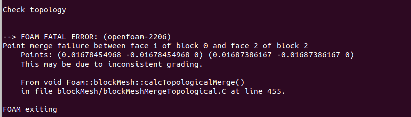 我这出现了这个错误,想问问李老师这个问题怎么解决呢?